A 3-phase alternator is a synchronous machine that converts mechanical energy into 3-phase electrical energy through the process of electromagnetic induction.
A 3-phase alternator, also called a 3-phase synchronous generator, has a stationary armature and a rotating magnetic field. In the three-phase alternator, the rotor winding (serves as field winding) is energized from a DC supply and alternate north and south poles are developed on the rotor.
Operation of Three-Phase Alternator
When the rotor is rotated (Let, anticlockwise direction) by a prime mover (engine, turbine, etc.), the stator winding (serves as armature winding) is cut by the magnetic flux of the rotor poles.
Due to electromagnetic induction, an EMF is induced in the armature winding. This induced EMF is alternating because the north and south poles of the rotor alternately pass the armature winding conductors. We can determine the direction of the induced EMF by Fleming’s right-hand rule.
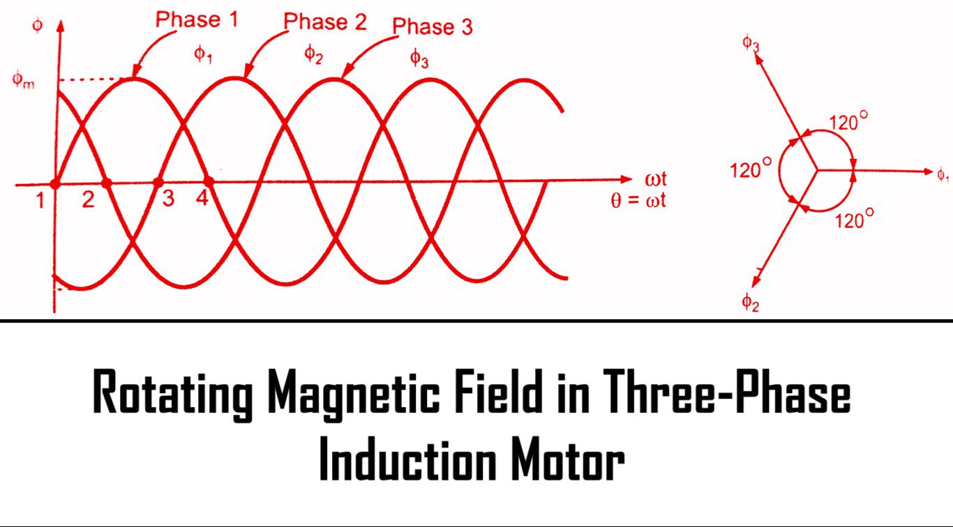
When the rotor is rotated a three-phase voltage is generated in the armature winding. The magnitude of the generated voltage depends upon the speed of the rotation of the rotor and the DC excitation current. However, the magnitude of generated voltage in each phase of the armature is the same, but displaced by 120° electrical from each other.
PDF Note of Three-Phase Alternator
- Construction of three-phase Alternator
- Derivation of emf equation of Three-Phase Alternator
- Chording Factor & Distribution Factor
- Armature Reaction at various pf conditions & concept of synchronous impedance.
- Voltage Regulation of three-phase Alternator by a) Synchronous Impedance method & b)mmf method
Download PDF Note of three-phase Alternator
Download PDF of Numericals on Alternator
I hope the above handwritten note can help you to understand the Three-Phase Alternator properly. Stay with us for more educational video lectures and handwritten notes with free job alerts as well.


Leave a Comment