What is Scott Connection or Scott-T Transformer?
The Scott-T Connection is the method of connecting two single-phase transformers to perform the 3-phase to 2-phase conversion and vice-versa.
The two transformers are connected electrically but not magnetically. One of the transformers is called the main transformer, and the other is called the auxiliary or teaser transformer.
The figure below shows the Scott-T transformer connection. The main transformer is center-tapped at D and is connected to the line B and C of the 3-phase side. It has primary BC and secondary a1a2. The teaser transformer is connected to the line terminal A and the center tapping D. It has primary AD and secondary b1b2 .
The identical, interchangeable transformers are used for Scott-T connection in which each transformer has a primary winding of Tp turns and is provided with tapping at 0.289Tp , 0.5Tpand 0.866 Tp.
Phasor Diagram of Scott Connection Transformer
The line voltages of the 3-phase system VAB, VBC, and VCA which are balanced are shown in the figure below. The same voltage is shown as a closed equilateral triangle. The figure below shows the primary windings of the main and the teaser transformer.
The D divides the primary BC of the main transformers into two halves and hence the number of turns in portion BD = the number of turns in portion DC = Tp/2.The voltage VBD and VDC are equal, and they are in phase with VBC.
The voltage between A and D is
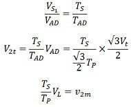
The teaser transformer has a primary voltage rating that is √3/2 or 0.866 of the voltage ratings of the main transformer. Voltage VAD is applied to the primary of the teaser transformer and therefore the secondary voltage V2t of the teaser transformer will lead the secondary terminal voltage V2m of the main transformer by 90º as shown in the figure below.
For keeping the voltage per turn the same in the primary of the main transformer and the primary of the teaser transformer, the number of turns in the primary of the teaser transformer should be equal to √3/2Tp.
Thus, the secondaries of both transformers should have equal voltage ratings. The V2t and V2m are equal in magnitude and 90º apart in time; they result in a balanced 2-phase system.
Position of Neutral Point N
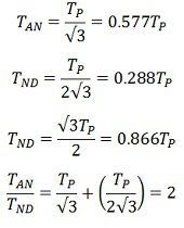
The primary of the two transformers may have a four-wire connection to a 3-phase supply if the tapping N is provided on the primary of the teaser transformer such that
The voltage across AN = VAN = phase voltage = Vl/√3.
Since the voltage across the portion AD.
The voltage across the portion of ND
The same voltage turn in portions AN, ND and AD are shown by the equations,
The equation above shows that the neutral point N divides the primary of the teaser transformer in ratio.
AN : ND = 2 : 1
Applications of Scott Connection
The following are the applications of the Scott-T connection.
- The Scott-T connection is used in an electric furnace installation where it is desired to operate two single-phase together and draw the balanced load from the three-phase supply.
- It is used to supply single-phase loads such as electric trains which are so scheduled as to keep the load on the three-phase system as nearly as possible.
- The Scott-T connection is used to link a 3-phase system with a two–phase system with the flow of power in either direction.
The Scott-T connection permits conversions of a 3-phase system to a two-phase system and vice versa. However, since 2-phase generators are not available, the converters from two phases to three phases are not used in practice.
Check out the given below pdf for the details of the Scott Connection or Scott-T Transformer.
PDF NOTE WILL BE UPLOADED SOON
I hope the above Hindi video lecture and the handwritten note can help you understand the Scott Connection or Scott-T Transformer. Stay with us for more educational video lectures and handwritten notes with free job alerts as well.


Leave a Comment